Update on Baero + Happy Holidays!

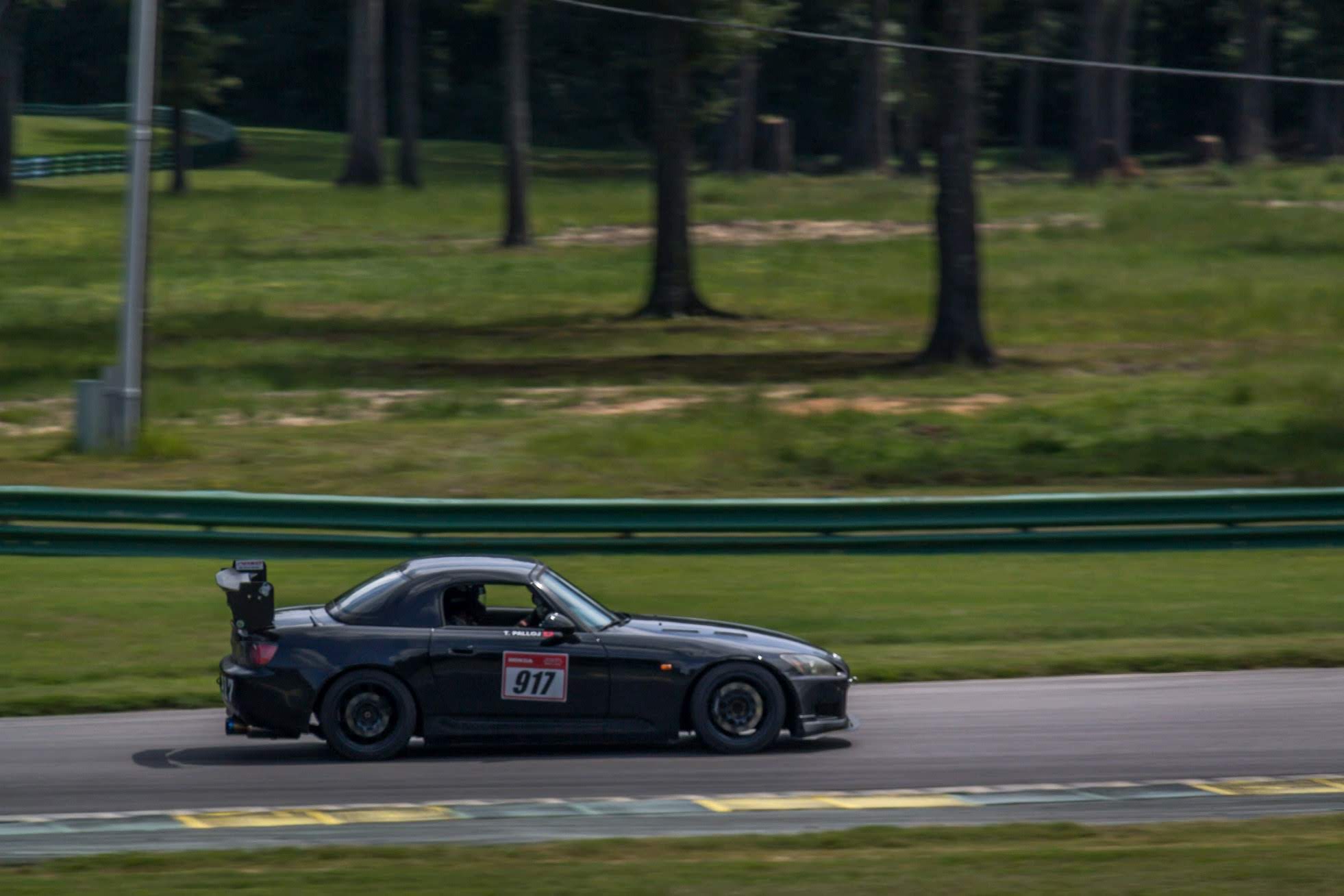
First and foremost I’d like to apologize for the lack of updates. I’ve had a few people ask for news on the 917 car and the shop. Don’t worry, they’re not going anywhere, sort of. Turns out I am moving from Orlando, FL to Detroit, MI. That’s right, motor city! Thanks to this site and all of my great friends/supporters/customers I was offered a position at Pratt&Miller as an Aero Engineer for their Corvette racing program. It is well and truly my dream job that I’ve wanted since I was a young teen. Therefore, orders for the next 1-2 weeks will be slightly delayed, but I definitely try and get them out ASAP. I want you guys ready for the 2019 season!

I’ve already learned a ton from my short time there and I can’t wait to be able to incorporate that knowledge on the 917 S2000 and offer even cooler parts for our cars. I already have some under splitter diffusers in the works. Since I installed the 9lives racing wing I have been lacking some front end grip. I could dial out some front sway bar, but my goal is to keep adding front grip to neutralize the car. Front dive planes and more will be added to the front splitter diffusers. I can’t wait to be able to share these products with you all! Give me a few weeks to get settled and I’ll be able to publish my results. I even got a better rig now, so the complexity will get much more serious!

I would also like to wish everyone a Merry Christmas, Happy Hanukkah, Kwanzaa, whatever! Take this time to really enjoy spending time with your family and friends. My move has definitely put a lot of things in perspective for me and really appreciate the people around me. As independent as I am, I wouldn’t be who or where I am today without them. It sounds cheesy, but customer support really does make a difference to small business owners like myself. There is nothing cooler than showing up to an event and seeing someone sporting my stickers or rocking my products. It is a truly humbling experience and I would like to thank you all for everything.

Make 2019 even faster!

Hand drawn version of my car from CarSplashART. Great prices and great results!

Hand drawn version of my car from CarSplashART. Great prices and great results!

VIR with NASA Mid-Atlantic

Sorry for the late update everyone, it's just been a really hectic month. I made the treck from Orlando to Virginia for the August 25/26 VIR event with NASA MA. I am trying to knock out all of my favorite childhood tracks one by one! PS: wait until you see which one is next.

upload.jpg

I don't own a truck/trailer so I had to drive the S2000 up. I was a little bit worried of the 10hr drive because the car isn't very comfortable at this point. The loud Tomei exhaust coupled with a Sparco containment seat aren't fun for long periods of time. However, as we began the trek, it actually wasn't that terrible. The excitement began to set in and time ended up flying by.

 I installed the Tomei silencer, which made the car as quiet as stock, but I think that's the issue for what's to come. For some reason, with the silencer installed the car would not engage VTEC. It would just sit at that RPM and burble. Removing the silencer proved that to be the problem because suddenly VTEC was back.

upload.jpg
upload.jpg

Once at the track though, all of those struggles were forgotten. Even disregarding the track, VIR is gorgeous. Everything was a lucious green, the weather was beautiful, and the people as friendly as ever. Even if I wasn't driving I wish I could go back and soak it all in again. 

The track itself was tricky during my first session. A Mustang owner wrecked so it got cut short after only a handful of laps. It took me 2-3 sessions in order to get my bearings on the line, but after that I was doing pretty well. I spent a lot of the weekend giving ridealongs to others that made the trip with us so I don't have any accurate representation of my pace. I was complaining about power loss to my friends because the car was going in and out of VTEC and the engagement point would change from lap to lap. With all that said, I managed a 2:18:x with passenger and loss of power. I don't think that's too bad for my first time there! 

 However, late Sunday evening things suddenly went South. I was out on my recon lap when I had no VTEC at all on the back straight. Going about 110MPH and the car would not accelerate. Couple seconds later and BOOM! Oil everywhere, smoke everywhere, metal chunks flying in my rearview mirror and the car turns off. I park on the side of the grass and have to be towed to the pits. My 185k AP1 block finally gave way.

upload.jpg
upload.jpg
upload.jpg

When tearing apart the motor, I believe the issue to be a failed rocker. The VTEC rocker on intake cylinder #3 had sheared. Therefore, I only had VTEC on three cylinders (hence me complaining about my power loss). That coupled with me continuing driving the car led to the failure. 

 However, a month later and I'm back on the road! This time with a good condition F22! I opted to keep my AP1 transmission as that combo sounds really enticing to me. Keep and eye out for a Sebring post next month to hear my thoughts!

upload.jpg

If you guys want a tutorial on how to do a motor swap on this car let me know and I will make one. It actually isn't too bad when you know what to do.

Voltex/J's Racing Endplates

After the success of the Baero APR custom endplates, I've been asked to repeat the study for Voltex Type 2 / J's Type 1 wings. I first started out by getting a template of the airfoil and endplate from a friend (Thanks Steve!). I used this to create a CAD model ready to be able to start my CFD analysis.

OriginalRender.JPG

The first thing I wanted to do was analyze the stock wing. This not only gives a benchmark to compare results to but also I was curious how it performed compared to the APR wing. The Voltex airfoil is definitely more efficient, but it does not produce the same downforce as a 3D APR wing, as expected. Below I will plot the surface plot and air trajectory on the stock wing, but I'll summarize the numerical results at the end. All results were done at 100MPH and 0 angle of attack.

StockTrajectory.JPG

Just looking at the surface plot on the leading edge it's obvious this wing will respond well to a more aggressive angle of attack. There is a big high pressure zone that I would want to relocate to the top surface of the airfoil by adjusting the AOA. This will add a little bit of drag but the tradeoff will be worth it.

Next I added my Baero APR endplates to the mix. I really wanted to make the same shape work to be able to benefit from lowering manufacturing costs, but it would not have it. They performed terribly. The Voltex wing did not like the notch at the top and the 12"x12" size was not performing well.

I then started with a base 12"x12" endplate and maneuvered it every which way to get optimal placement. Downforce spiked, but so did drag. The good news is this showed me I was able to scavenge more downforce from this wing. I then began to adjust the shape to be able to keep my downforce but reduce the drag levels. Here are the plots of the final wing design:

The results of the new endplates ended up even better than I expected. Downforce was increased by ~33%, drag by only ~3%, and a whopping ~30% increase in efficiency. Here are the final charts to show a few different results I got. These will be added to my shop very soon!

Palm Beach with NASA

Less than a month before I blew the cylinder head at Sebring I was able to attend another NASA event - Palm Beach International Raceway (PBIR). I was a little worried before the weekend because I barely got to drive the car and test it out. I ended up installing a mint AP2 head onto my AP1 block, but while I was in there I did a new Koyo radiator and upgraded to head studs. A couple little things were added too: like a catch can so I don't smoke screen people and I did the throttle body coolant bypass.

It turns out my worries were a little exaggerated as the car performed flawlessly. I drove 3 hrs down to the track, did 8 total sessions over the weekend, and drove it right back without any hiccups. With the refresh the car is so much more lively. No longer are other S2Ks pulling me on the straights and it feels genuinely faster. Thankfully I have AP2 valve spring retainers now so I have a little money shift insurance.

Here is a picture of Dave and I having fun:

This next one is my favorite photo of the weekend. Dave, Jeff, and myself went out together to have some fun. It felt like we were running an S2K train passing everyone.

The next adventure will take us to VIR at the end of August. It will be a mighty long drive, but another bucket list item will be crossed off!

Splitters - Size Does Matter!

You know what they say: bigger is always better. Turns out that's exactly the case for front splitters. I recently got tasked with a project for a good friend of mine - find out the best splitter size. I currently have a 2" front splitter on my AP1 and it worked great when the car was dual purpose. But now that it is a dedicated track only car, I thought 2" wasn't going to cut it. After further research that's exactly the case.

To give a little more background before I get to the nitty gritty stuff, the main purpose is to find the best splitter that complies with NASA Time Trial rules (specifically TT4 in this case). This makes it easy on my end since they only allow perfectly flat splitters and it can only extend 4" past the body. I do plan on doing some research on how much benefit spats and winglets do, but for the time being the variable in question here is size.

First thing I did was scan my front end. I only show my bumper here, but I have a scan of most of the car at this point. I would have loved to do the whole thing, but it takes about a half hour to just analyze the bumper and it's dangerously close to crashing my graphics card. Here are some shots of my model:

Splitter_Front.JPG
Splitter_Top.JPG
Splitter_Side.JPG

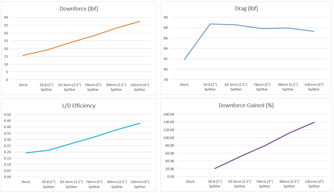
What I did was initially run my CFD model with just the bumper by itself. These are the numbers that I am using as my baseline. Don't take stock into the numbers themselves, but only the differences. Once that was achieved I took measurements at 2", 2.5", 3", 3.5", and finally 4" past the bumper. The thickness of the splitter is kept constant throughout.

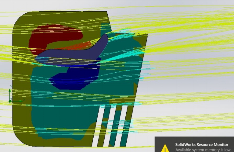
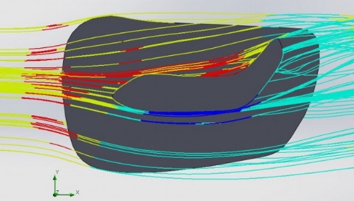
Here is a cool shot I took showing the air path and surface plot on top of the splitter. You can see the highest pressure is right in front of the bumper! I tried to show the trajectory around the entire bumper but my computer crashed! I can really only render small pieces at a time.

Splitter_IG1.JPG

Now the results are displayed below. As you can see, as the size of the splitter is increased so too is the downforce. The good part is the added drag is pretty much negligible as you increase size, so the only downsides are a little bit extra weight, and it's much harder to get the car on the trailer. What I plan on doing is creating quick disconnect brackets for my splitter, so I don't have to touch the front bumper to take it off. This will allow me to keep it off the car while trailoring and put it on the car once I am at the track in only a few minutes.

Graphs.JPG

4" splitter here I come!

Sebring Summer Sizzler

Just a weekend after Road Atlanta, I attended another NASA event - this time at Sebring International Raceway! Even with the hot Florida summer attendance was full. The car was definitely down on power in the heat, but it was still a really fun weekend. Here are some photos:

7R6A8841.jpg
7R6A6130.jpg
F74G8926.jpg
IMG_6945.jpg

Unfortunately my luck ended on the last session of the second day. I miss-shifted after turn 7 going from 3rd to 4th gear. Turns out I went to 2nd for a split second, causing an overrev. The pics below illustrate exactly what happened to 6/8 of my intake retainers. You can also see my bent valve on cylinder 4. My compression numbers went from 240 across the board to 120/210/180/0. As soon as I ran compression I knew I had bent valves, even before I popped the valve cover off.

The good news is I did not drop a valve. After taking off the head this past weekend the pistons have no scars and cylinder walls are buttery smooth. A spare head is in the mail as we speak. Turns out the car will only be down for a few weeks. VIR at the end of August is still happening!

While I'm down there I'm going to go ahead and do a few upgrades: ARP studs, new Koyo radiator, and a full gasket kit.

20180630_184532.jpg

A new challenger appears!

Now that the S2000 is a full track car I really needed a more livable DD. I was driving a crossover to work and it was getting really boring. I hate automatics and wanted something fun and easy to drive. I had narrowed my search down to either a ND Miata or FRS/BRZ. Another goal of mine was to have a backup track car if I ever have issues with the S2K (knock on wood). 

I think I hit all of my checkboxes. Ended up getting a 2013 FR-S in "Whiteout". It is very tastefully modded by another track enthusiast: Wilwood BBK, lowering springs, Enkei wheels with Hankook RS3's, and lastly an oil cooler to make sure it does not overheat at the track. I actually like it a lot more than I thought I would. It's a perfect daily driver and it's added practicality has already come in handy. If this platform had a screamer like a F20/F22 it would be a game changer.

If you hadn't guessed, parts for this platform will soon be in development! Keep your eyes peeled.

PART_1527854546540.jpg

Road Atlanta

What a weekend! Went up to drive Road Atlanta this past weekend with some good friends. I ended up driving a friend's track prepped AP2 S2000, rather than my own. Maybe that was a bad idea because I now wish my car was setup the same way! The two things that really stuck out to me is the lower VTEC engagement point and how much better his braking is. He is running the Stoptech ST40 kit, while I am on a Wilwood BBK. I am swapping to a more aggressive pad setup (DTC-60s up front) to see if I can replicate it. If I keep having soft pedal issues and extreme pad taper, then I am going to ditch my Wilwood setup. The lower VTEC is a must as well, especially since I have an AP1 with longer gearing.

Here are some of my favorite pictures from the weekend. If you've never driven Road Atlanta I highly recommend it. It's a whole different animal than the FL tracks I'm used to since there are mid-corner elevations changes, blind corners, and a lot of high-speed flat turns. It was a blast to drive. Even after a 2-day weekend, I was ready to go back on Monday morning.

My favorite shot of the weekend. This is at the bottom of Turn 12, going down the mountain(!!) of a hill to the front straight.

My favorite shot of the weekend. This is at the bottom of Turn 12, going down the mountain(!!) of a hill to the front straight.

Point me by please..

Point me by please..

Now that's better

Now that's better

Test and Tune Weekend

Went to the FIRM again this past weekend to get the car ready for a busy summer. I am driving Road Atlanta with NASA SE on June 16/17 and then Sebring with NASA FL on June 23/24. I wanted to make sure the car is exactly how I want it and it didn't let me down.

I recently sold my SSR GTV02 (17x9+45 square w/ Dunlop Star Spec V2) to my brother and mounted the Wedsport TC105N (17x9+49 square) that I've had sitting in the shed. I was kind of on the fence about the blue/teal color, but I love how they look on the car.

I managed to scoop up the Kumho V720 that were on clearance on Tirerack. $300 for 255/40/17 200TW tires had me excited. My expectations were low, but they're going to be a fun tire for a few events. While they don't have the same grip that my Star Specs or RS4s did, they were very predictable. It was easy to sense what the car was doing and corrections were simple. I could hear and feel when they were on the edge. I slid way more running these tires, but I was having a blast. I was 2 seconds slower on these compared to the Star Specs, but I was fighting air in my brake lines all day, and I was not running my hardtop this time. The lack of aero was evident on the one session I ran with the top down.

Here are a few pics of the weekend:

The Case of the Bent Trunk - Solved!

I've had a few guys message me if I can try and prevent their trunks from bending when they install a Voltex, or other, wing. I didn't know this was a thing but apparently mine has the same problem. My APR wing has ever so slightly bent the sides of my trunk.

Therefore I began to look into this problem a little further. Research on the internet speculates that the added downforce bends the trunk, but I am skeptical that the downforce produced by our cars can cause this. I had a friend send me his rep Voltex hardware to get some measurements from. It turns out the baseplates they provide are perfectly flat. This is a problem because the trunk is not flat at all, but has a complex curved surface. When tightening the baseplate on the trunk one of the two will deform to fit the other. The axial strength of aluminum is much lower than a FRP composite so of course the trunk deforms to fit the endplate.

I took some measurements of my trunk and put together a simplified stress model to see how the trunk reacts under downforce. This is not a 100% accurate model, but it serves it's purpose to show the load path and some results to determine paths forward.

I setup my model using 6061 aluminum for the trunk, rubber for the trunk supports, and FRP for the endplates. I constrained it in the y-direction on the rubber stoppers and also constrained the trunk where it mounts to the frame. I added 400lbf of downforce to the endplates since I could not find online how much the Voltex wing generates.

The results can be seen in the pictures below, but the displacement is low as I expected (.006"). The max stress is 12ksi. However the max displacement is right where we are seeing the bending in the above picture, so maybe there is some merit to the study.


My plan is to redesign the baseplates and wing stand mounts to better distribute the stress across the trunk. My goal is to reduce max stress from 12ksi to 4ksi and more importantly provide a profile that fits the trunk.

I was also not a fan on how the baseplate to wing stand brackets are in a single shear condition. This seems like a very weak part of the wing design that I plan on fixing with my new baseplates. I was to change it to a double shear condition and remove the hardware from a direct shear load.

UPDATE:

After spending some design time, I think I have the solution to the problem at hand. The goals I initially set to achieve (reducing stress by 1/3 and matching the trunk profile) have both been achieved.

Here is the new stress plot. As you can see the peak stress was reduced from 12.18 ksi to 3.62 ksi. That's just over 70% reduction in stress on the trunk! More importantly, the stress concentration when the bends were seen have been eliminated.

Stress_Final.JPG

Below is the new displacement plot. Max displacement was reduced from .0062" to .0025", a reduction of over 40%!

Displacement_Final.JPG

Here is a look at the profile of the bottom of the baseplate so that is can sit flat on the trunk. I printed a test piece and it sits perfectly on the bottom of my trunk. Most of the bending is from installation since the original Voltex baseplates were perfectly flat. These will not cause the trunk to conform to it, therefore preventing bending.

Trunk Profile.JPG

To take it one step further, I think proper installation should also be followed. The trunk should be loosened from the frame mounts so that is completely unstressed. Then I would hand-tighten all of the new baseplates bolts, stand bolts, and wing bolts in stages (think a cam install). So handtighten everything, then go in 5 ft-lb stages until you get to the final torque. We want to easy the trunk into it's final shape to prevent any strain.

My next steps are to bring these into production. Since they are in direct sunlight I cannot fab them out of PLA. I am going to do some tests in PETG and ABS and have them sit in the sun for a few days. If they pass the test, then they will be put up for sale.

Here's a view of the final shape:


Baseplate_FinalView.JPG

Endplates: The Making Of

It's always amazing to see designs come to life.

After putting up my blog about my end plates, I reached out to a very talented friend of mine to help in the building process.  Mike and I used to work together and he was up for the task of cutting out my end plates.  He did an incredible job and I could not be happier with the results.

I'd highly recommend subscribing to Physics Anonymous to see more.  They're hobbyists at it's finest.

Finished Endplate Study

The endplate analysis is finally done. I've been spending the past week trying to find a machine shop to mill my low quantities. I tried cutting them on my desktop CNC, but it's not quite stiff enough to cut 6061 aluminum. I then cut one by hand with my angle grinder just for test fitment. The car felt much more planted on the highway, and I really like how aggressive the car looks with the bigger endplates. Once I find someone that will produce them at a reasonable cost, I will add them to the site for purchase. I'm trying to keep them as cheap as possible. I really doubt I'll make any money off of them.

Anyways, I'll get around to posting my results now. I began by taking the downforce/drag on the stock endplates. I am going to post my data related to these since they don't have much bearing on their own. The numbers will change slightly depending on the car the APR GTC200 wing is mounted to and the height that it is installed at. I don't have the riser's yet, but I need to get them after going to my new endplates.

All calculations were done at a velocity of 100mph and 0 angle of attack. I am going to have another post that shows stock vs. my endplates at different angles of attack. One of the main benefits of bigger endplates is you can reduce the angle of attack, effectively reducing drag, while still having adequate downforce.

The design ideas that I explored, even though not all are shown, were:

  • Endplate Size
  • Endplate Location
  • Fillets/chamfers on corners vs. square
  • Notch, notch shape, notch location
  • Slots, slot location, slot size
  • Gills, gill location, gill size
  • Numerous combinations of the above

It would be quite cumbersome if I posted all of the data, so I boiled it down to the results that had the most impact. I'd like to think I covered all of my bases.

Here is the flow plot and vortex of the stock endplates. L/D for the stock endplates was 3.65.

Stock endplate flow plot (these are the "old" APR endplates and wing, since that is the wing I have on my S2000.

Stock endplate flow plot (these are the "old" APR endplates and wing, since that is the wing I have on my S2000.

Vortex generated by the stock endplates.

Vortex generated by the stock endplates.

The first thing I did was just change the dimensions of the endplates to 12"x12" (this is the maximum size allowed by many racing organizations, like NASA).  You can see the surface plot is less than ideal. There is a high pressure area right at the frontal area of the airfoil resulting in tons of drag. With just the 12"x12" endplates, downforce increased by 10.35% but L/D dropped to 2.92 (a 20% decrease in efficiency). 

Surface plot of 12"12" endplate with 2" fillets

Surface plot of 12"12" endplate with 2" fillets

Flow diagram of the 12"x12" endplates with 2" fillets on each corner

Flow diagram of the 12"x12" endplates with 2" fillets on each corner

I was extremely let down by the initial data, so I began to play with the location of the endplates a little bit. This is where the surface plots really come in handy. We want the max pressure to be right on top of the airfoil and the min pressure right below it. This will create the maximum amount of downforce.

The next thing I did was move the location of the endplates incrementally aft until my L/D stopped increasing. Just doing this kept the downforce of the larger endplates, but removed the drag penalty. This resulted in L/D climbing to 3.90 (a 6.9% increase in efficiency). I was quite shocked just a small change in placement could have such a dramatic effect on the wing efficiency, especially with an endplate so large.

Before I start looking into some of my other ideas, I decided to maximize efficiency just by playing with the location. Playing with dozens of combinations, I ended up with a maximum L/D of 4.09 (a 12.19% increase in efficiency).

The first design idea I implemented was the rear notch. This not only is good for decreasing drag, but it will reduce the weight of the endplates. I think they look really cool too. I tried different combinations such as shape, square vs. chamfer, fillets vs. no fillets, location and got the best results when the notch is inline with the aft most point of the airfoil. Adding the notch dropped my downforce increase ever so slightly, but improved drag by a decent amount. This jumped the efficiency to 12.5%. Not a huge increase from before, but I'll take anything I can get that also drops weight.

Square notch with fillets

Square notch with fillets

Chamfered notch

Chamfered notch

I also played with a few different designs for slots. I was really optimistic about the slots as they play a big role in vortex generation. With optimal slots I was able to increase the efficiency to 12.63%, which is a small improvement. I did not deem them worthy enough of the machining costs to keep them in my design. Also, if I end up making ABS versions I do not find them stiff enough at higher speeds. Therefore, even though the slots were benefitial in the long run it does not justify the costs in my mind.

Medium sized slots

Medium sized slots

Higher slots

Higher slots

Top view of flow with the added slots

Top view of flow with the added slots

Vortex generation by added slots. The higher velocity can be seen compared to the plot without slots

Vortex generation by added slots. The higher velocity can be seen compared to the plot without slots

The final idea I want to go over is adding gills. This is kind of a weird concept because it allows the high pressure air above the wing to evacuate, which is NOT what we want. We want to keep the higher pressure above the wing to produce more downforce. However, many F1 teams have found great success pairing gills with slats so I have always wanted to give it a try. I don't think these would be legal anyways since they increase the wingspan (10mm is max allowed endplate width), but I was curious.

Having just the upper gills I was able to reduce drag, but it also reduced downforce resulting in a lower efficiency than previous designs I've covered.

Adding slots to the gill design further decreased drag, but I wasn't able to get downforce back to where I wanted it to increase the efficiency. Therefore no gills and slots were added to the final design.

Added gills above airfoil

Added gills above airfoil

Gills working in conjunction with lower slots

Gills working in conjunction with lower slots

Taking all of my findings I kept playing with slightly different geometries to get my final design. I wasn't a big fan of having a mostly square endplate with a notch, so once I got the required results I was trying to make them look "cooler" without sacrificing performance. 

I printed a fitment piece and found it bolted right up to the drivers side, but I needed the hole slightly shifted to fit perfect on the passenger side so I added a slot to the rear mounting hole so it can have a little adjustment. The airfoil has inserts in the composite and installing them isn't very accurate so I wanted to account for that in my design.

With the final design, at 100mph and 0 AOA the results are:

19.10% increase in downforce and a 13.18% increase in wing efficiency. Not bad at all!

Final endplate shape

Final endplate shape

Downforce.JPG

AP2 Cooler Ducts are Finished!

I made these for a friend of mine that is planning on running an intercooler on each side of his bumper (Porsche GT2RS style). These take air from the front bumper, just like our brake ducts, and funnel that air into your cooler. These are perfect for putting an oil cooler inside of your fender liner so that you don't block off air from the radiator. They are super lightweight with a 0.15" wall thickness.

It ended up being the biggest piece I have ever made. It is much larger than my machine's capabilities (12"x12"x15") so I ended up printing it in 3 separate pieces. I then "welded" those pieces together using my soldering iron since the melting temp of PLA is around 200C. 

I can't wait to see how these look and function installed!

Here is when we test fitted them on his car. The Stoptech Trophy kit sure in beautiful by the way..

IMG_20180331_161631.jpg
CFD analysis I conducted at 100MPH, atmospheric pressure at outlet to see how the air would behave. This was an iterative process to get the best possible velocity field.

CFD analysis I conducted at 100MPH, atmospheric pressure at outlet to see how the air would behave. This was an iterative process to get the best possible velocity field.

Finished product

Finished product

Finished product

Finished product

Designing better APR GTC200 Endplates

A while back I started a thread about designing my own wing. I ended up getting sidetracked and never finishing it as I found a dirt cheap S2000 specific GTC200 online. However, now that I am finished designing the brake ducts I've diverted my attention to making "better" endplates for my wing.

I took out the 3D scanner tonight and got a profile of the outward profile of the wing, as well as the endplate profile. Made a quick model and ran some CFD to see how the pressure plots looked on the current endplates, which I show below. I used the same profile throughout, even though that is not the case, because my gaming laptop cannot handle CFD any more complicated than this. I can't even save cut plots as is, I can just quickly view them until my computer crashes. I'll try and find a way of saving to show you guys as that is where the best data really is.

Options I plan on exploring:

1.) Size (max being the allowable 12"x12")
2.) Louvres
3.) Slats
4.) Splots
5.) Notch on top aft section
6.) Shape

Pretty much I am going to mimic a lot of the modern F1 wing designs, even though they use a dual airfoil. Whichever one gives me the best results I am going to produce and add to my product line.

Tips/Suggestions/Criticism is very welcome. My first goal is to calculate baseline lift/drag ratio of this wing so I have something to compare against.

Pressure trajectory plot (red is highest pressure, blue is lowest pressure):

Flow1.jpg

Airflow behind the endplate, showing the vortex and trapped air:

Flow2.jpg

Day at The Firm

It's been a year and a half since I last tracked my S2000. I've added a lot of parts since to make it tracked focused.  It's running new tires (255/40/17 Dunlop Star Specs), new SBG Wilwood Front BBK, aero, and just picked up this replica Amuse top the day before the event.  My best time was 1:23.1, which is a personal best!  I'll be headed to Sebring next.

It took a few sessions to catch up to the confidence the wing gives you and the shorter stopping time, but I ended up dropping 2 full seconds from my personal best.

My next goal is to drop as much weight as I can while maintaining the street driveability the car has now.

00000IMG_00000_BURST20180414083056738_COVER.jpg
 
IMG_20180414_113034.jpg
IMG_20180414_113048 (1).jpg
Absolutely loved this GT3RS. Sounds absolutely amazing and he was terrorizing everyone on the track!

Absolutely loved this GT3RS. Sounds absolutely amazing and he was terrorizing everyone on the track!

Showing Off Our New Logo

baero 3.png

We are proud to announce that baero has a new logo!  It was inspired by the black and white filament used in the 3D printing process of some of our parts.  This logo was wonderfully designed by me, Jami! 

Let us know your thoughts!