The endplate analysis is finally done. I've been spending the past week trying to find a machine shop to mill my low quantities. I tried cutting them on my desktop CNC, but it's not quite stiff enough to cut 6061 aluminum. I then cut one by hand with my angle grinder just for test fitment. The car felt much more planted on the highway, and I really like how aggressive the car looks with the bigger endplates. Once I find someone that will produce them at a reasonable cost, I will add them to the site for purchase. I'm trying to keep them as cheap as possible. I really doubt I'll make any money off of them.
Anyways, I'll get around to posting my results now. I began by taking the downforce/drag on the stock endplates. I am going to post my data related to these since they don't have much bearing on their own. The numbers will change slightly depending on the car the APR GTC200 wing is mounted to and the height that it is installed at. I don't have the riser's yet, but I need to get them after going to my new endplates.
All calculations were done at a velocity of 100mph and 0 angle of attack. I am going to have another post that shows stock vs. my endplates at different angles of attack. One of the main benefits of bigger endplates is you can reduce the angle of attack, effectively reducing drag, while still having adequate downforce.
The design ideas that I explored, even though not all are shown, were:
- Endplate Size
- Endplate Location
- Fillets/chamfers on corners vs. square
- Notch, notch shape, notch location
- Slots, slot location, slot size
- Gills, gill location, gill size
- Numerous combinations of the above
It would be quite cumbersome if I posted all of the data, so I boiled it down to the results that had the most impact. I'd like to think I covered all of my bases.
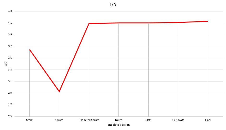
Here is the flow plot and vortex of the stock endplates. L/D for the stock endplates was 3.65.

Stock endplate flow plot (these are the "old" APR endplates and wing, since that is the wing I have on my S2000.

Vortex generated by the stock endplates.
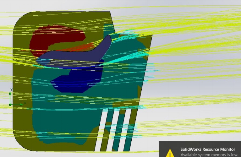
The first thing I did was just change the dimensions of the endplates to 12"x12" (this is the maximum size allowed by many racing organizations, like NASA). You can see the surface plot is less than ideal. There is a high pressure area right at the frontal area of the airfoil resulting in tons of drag. With just the 12"x12" endplates, downforce increased by 10.35% but L/D dropped to 2.92 (a 20% decrease in efficiency).

Surface plot of 12"12" endplate with 2" fillets

Flow diagram of the 12"x12" endplates with 2" fillets on each corner
I was extremely let down by the initial data, so I began to play with the location of the endplates a little bit. This is where the surface plots really come in handy. We want the max pressure to be right on top of the airfoil and the min pressure right below it. This will create the maximum amount of downforce.
The next thing I did was move the location of the endplates incrementally aft until my L/D stopped increasing. Just doing this kept the downforce of the larger endplates, but removed the drag penalty. This resulted in L/D climbing to 3.90 (a 6.9% increase in efficiency). I was quite shocked just a small change in placement could have such a dramatic effect on the wing efficiency, especially with an endplate so large.
Before I start looking into some of my other ideas, I decided to maximize efficiency just by playing with the location. Playing with dozens of combinations, I ended up with a maximum L/D of 4.09 (a 12.19% increase in efficiency).
The first design idea I implemented was the rear notch. This not only is good for decreasing drag, but it will reduce the weight of the endplates. I think they look really cool too. I tried different combinations such as shape, square vs. chamfer, fillets vs. no fillets, location and got the best results when the notch is inline with the aft most point of the airfoil. Adding the notch dropped my downforce increase ever so slightly, but improved drag by a decent amount. This jumped the efficiency to 12.5%. Not a huge increase from before, but I'll take anything I can get that also drops weight.

Square notch with fillets

Chamfered notch
I also played with a few different designs for slots. I was really optimistic about the slots as they play a big role in vortex generation. With optimal slots I was able to increase the efficiency to 12.63%, which is a small improvement. I did not deem them worthy enough of the machining costs to keep them in my design. Also, if I end up making ABS versions I do not find them stiff enough at higher speeds. Therefore, even though the slots were benefitial in the long run it does not justify the costs in my mind.
Medium sized slots

Higher slots

Top view of flow with the added slots

Vortex generation by added slots. The higher velocity can be seen compared to the plot without slots
The final idea I want to go over is adding gills. This is kind of a weird concept because it allows the high pressure air above the wing to evacuate, which is NOT what we want. We want to keep the higher pressure above the wing to produce more downforce. However, many F1 teams have found great success pairing gills with slats so I have always wanted to give it a try. I don't think these would be legal anyways since they increase the wingspan (10mm is max allowed endplate width), but I was curious.
Having just the upper gills I was able to reduce drag, but it also reduced downforce resulting in a lower efficiency than previous designs I've covered.
Adding slots to the gill design further decreased drag, but I wasn't able to get downforce back to where I wanted it to increase the efficiency. Therefore no gills and slots were added to the final design.

Added gills above airfoil

Gills working in conjunction with lower slots
Taking all of my findings I kept playing with slightly different geometries to get my final design. I wasn't a big fan of having a mostly square endplate with a notch, so once I got the required results I was trying to make them look "cooler" without sacrificing performance.
I printed a fitment piece and found it bolted right up to the drivers side, but I needed the hole slightly shifted to fit perfect on the passenger side so I added a slot to the rear mounting hole so it can have a little adjustment. The airfoil has inserts in the composite and installing them isn't very accurate so I wanted to account for that in my design.
With the final design, at 100mph and 0 AOA the results are:
19.10% increase in downforce and a 13.18% increase in wing efficiency. Not bad at all!

Final endplate shape